
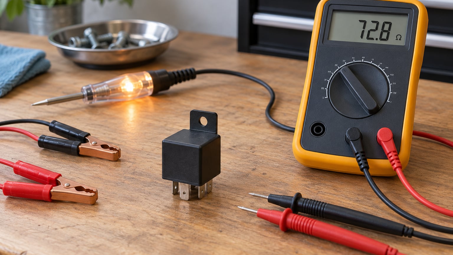
How to test a car relay takes about five minutes with a multimeter. You check two things: the coil resistance between pins 85 and 86, and the switch contacts between pin 30 and pin 87 or 87a. A healthy 12V automotive relay reads somewhere around 50 to 120 ohms across the coil, shows no continuity on the normally open pair until you power the coil, and clicks audibly when energized.
A relay is a cheap plug-and-play switch, and it fails far more often than the electronics it feeds. Confirming one in either direction takes less time than the drive to the parts counter.
Before you pull anything, note that a relay can test perfectly and still be the wrong suspect. Corroded socket pins, a blown fuse and a bad ground all mimic a dead relay. The last method below covers how to tell the difference.
Table of Contents
What You Need
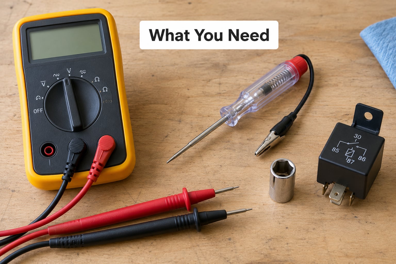
- A digital multimeter. Any meter with an ohms setting and a continuity beep works. A manual-range meter set to its lowest ohm range gives the most accurate coil reading.
- A 12V power source. The vehicle battery and a pair of jumper leads will do. A 9V battery is safer on the bench but often too weak to actuate a full-size automotive relay.
- A test light or small bulb and holder. Useful when you want a visible load instead of a number.
- A relay socket or a known-good socket lead so you can energise the coil without crushing the pins with alligator clips.
- The wiring diagram for your vehicle, plus the relay part number. This tells you which circuit the relay controls and which pins the socket uses.
Safety first: disconnect the negative battery terminal before measuring resistance. Resistance readings with the battery still connected are meaningless and unstable. When you apply power to the coil, connect pin 86 to positive and pin 85 to negative. Some relays carry an internal flyback diode, and reversing that polarity can damage the relay or, on a car, the module that drives it.
Also read the diagram printed on the relay housing before you do anything else. Pin 85 and 86 are the coil. Pin 30 is common, pin 87 is the normally open output, and pin 87a is the normally closed output on five-pin relays. The physical position of those pins around the housing does not always match the printed diagram, so go by the numbers, not by where the pins sit.
Step-by-Step: How to Test a Car Relay
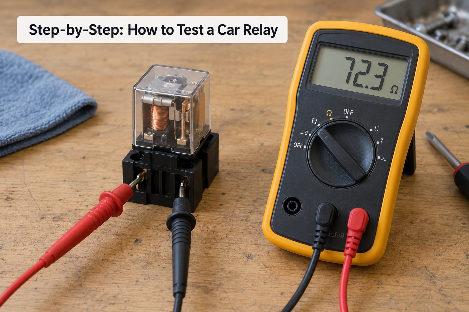
Five methods, roughly in order of how often they give a clear answer. The first two are bench tests with the relay removed. The third is done in the car. The fourth and fifth are for when you have no meter, or when the relay passes everything and the fault is still there.
| Pin | Function | De-energized | Energized |
|---|---|---|---|
| 85 | Coil, ground side | No voltage | 12V |
| 86 | Coil, power side | No voltage | 12V |
| 30 | Common, from battery or fuse | Source of power | Source of power |
| 87 | Normally open output | Open, no continuity to 30 | Closed, under 1 ohm to 30 |
| 87a | Normally closed output (5-pin only) | Closed, under 1 ohm to 30 | Open, no continuity to 30 |
Normally open and normally closed describe the relay with no power applied. That trips people up: a normally closed 87a circuit showing continuity is correct when the relay sits on the bench unpowered, not a sign of a fault.
How to Test Relay Coils for Continuity
Set the meter to ohms on the lowest range and probe pins 85 and 86. A healthy coil reads between roughly 50 and 120 ohms, though many automotive relays land between 40 and 200 ohms and still work fine.
An open circuit reading, OL or infinite resistance, means the coil is broken. Zero ohms means the coil is shorted. Either way the relay is finished.
A small reading is not a failed coil. A coil of 150 ohms still works; it just needs a slightly higher voltage to actuate, and the vehicle battery provides that. Only a reading outside the plausible band, or a wildly unstable one, points to a problem.
How to Check Relay Contacts with a Multimeter
Leave the meter on continuity and probe pins 30 and 87. With no power on the coil you should get nothing, because that pair is normally open.
Now apply 12V to the coil: pin 86 to positive, pin 85 to negative. You should hear a click and the 30 to 87 reading should drop to under 1 ohm. That flip is the whole test.
On a five-pin relay, probe 30 to 87a first. Unpowered it reads under 1 ohm; once the coil is energized it goes open while 30 to 87 closes. The two outputs swap states, which is exactly what a healthy relay does.
| Probe pair | Expected reading | Verdict |
|---|---|---|
| 85 to 86, unpowered | 40 to 200 ohms | Good coil |
| 85 to 86, unpowered | OL or infinite | Open coil, relay is dead |
| 85 to 86, unpowered | 0 ohms | Shorted coil, relay is dead |
| 30 to 87, unpowered | Open | Correct, normally open |
| 30 to 87, energized | Under 1 ohm | Good, contacts close |
| 30 to 87, energized | Still open | Contacts burnt or relay is not actuating |
| 30 to 87a, unpowered | Under 1 ohm | Correct, normally closed |
| 30 to 87a, energized | Open | Correct, contacts open |
How to Perform a Voltage-Drop Test
If you want to know how to test a car relay while it is still wired in the car, this is the method, and it finds faults a bench test cannot. Leave the relay in the socket and set the meter to DC volts.
With the circuit commanded on, measure from the power side of the socket to battery negative. Then measure from the output side of the socket to battery negative. Both should read close to battery voltage.
Any gap of more than about 0.5 volts between the two readings points at the relay contact and its socket pins. A big gap between battery voltage and the input side means a bad fuse, a poor main ground, or damaged wiring upstream. If the output reads nothing at all, jump pin 85 to ground briefly: if the relay clicks and the device works, the control circuit is your problem, not the relay.
How to Use a Test Light or Small Load
Without a multimeter, you can still get an answer. Ground the negative lead of a test light firmly on a clean chassis ground, then touch the positive lead to pin 30 and then to pin 87.
Pin 30 should light, because it carries constant battery power. Pin 87 should stay dark. Bridge pin 85 to ground with the light still on pin 87, and the relay should click and the light on pin 87 should come on.
Never bridge 30 to 87 directly with the circuit live and a high-current device connected. That is a dead short across the battery, and the load is what the relay exists to isolate.
The swap test is worth mentioning too. Mechanics often substitute a known-good relay rather than trusting a meter reading alone, and a relay that behaves correctly in another socket is almost certainly fine.
How to Confirm a Relay Is Not the Problem
When the relay passes every bench test but the symptom is still there, work outward from it rather than ordering another relay.
- Battery and main grounds. Check that the battery is charged and that the negative cable is tight and free of corrosion. A weak battery often produces a click without a full actuate.
- The fuse. Confirm the circuit fuse is intact and that the socket pin has not corroded and widened. A loose socket terminal looks fine until you wiggle it.
- The socket itself. Pull the relay out and look at the pins. Green deposits or heat discoloration mean the socket needs cleaning before you judge the relay.
- The control circuit. With the relay pulled, activate the original switch or command and measure at socket pin 86. No voltage means the problem is upstream of the relay.
- The wiring. A voltage drop of more than 0.5 volts anywhere in the path means damaged wire, a corroded connector, or a bad connection somewhere along the run.
- Then the module. Only once power, ground, fuse and wiring check out is the control module a sensible suspect.
Common Mistakes
Measuring resistance with the battery connected. The meter sees the vehicle’s electrical system on top of the coil and the reading becomes noise. Disconnect the battery first.
Using auto-range by default. Auto-range often picks a range too high to resolve a 50 ohm coil cleanly. Switch to the lowest ohm range and the number settles down.
Trusting pin positions instead of pin numbers. On plenty of relays the physical layout does not match the diagram printed on the case. Read the numbers.
Treating a high coil reading as a fault. A 150 ohm coil is normal for many relays. Only infinite or near-zero readings are meaningful failures.
Reading 87a continuity as a dead contact. That pair is closed when the relay is unpowered. Test it again with the coil energized before condemning anything.
Replacing the relay before checking the socket. Reseating a relay in its socket often restores operation temporarily by breaking up corroded contact surfaces, which sends people back to the parts counter for a second relay.
Applying 12V backwards. Where a flyback diode is fitted internally, reverse polarity can destroy the relay and stress the driving module. Polarity first, power second.
If the relay comes back healthy but the symptom stays, the next things to look at are the fuse and the socket pins. Both how to test a fuse in a car and how to test a car battery at home are quick checks, and a weak battery is the classic reason a relay clicks without fully actuating. If the whole circuit checks out and the engine will not crank, move on to how to test a starter motor.
Frequently Asked Questions
Can I test a car relay with a multimeter?
Yes. A multimeter checks coil resistance between pins 85 and 86, and contact continuity between pin 30 and pin 87 or 87a. Disconnect the battery before pulling the relay and before any resistance reading. A healthy coil sits roughly between 40 and 200 ohms.
What resistance should a car relay read?
Most healthy 12V automotive relay coils measure somewhere between 50 and 120 ohms, and plenty of working relays read up to 200 ohms. An infinite or OL reading means the coil is open. Zero ohms means it is shorted. A small resistance alone is never a failure.
Why does my test light work but the relay does not switch?
A test light proves voltage is present, not that the relay closes the circuit. Check that the light is grounded to clean chassis metal and that you are touching the intended pin. Then power pin 86 and ground pin 85 directly. If the relay still does not click, the coil or the socket is at fault.
Can a relay be faulty even when it clicks?
Yes. A relay can actuate audibly and still fail to carry current, because its contacts are burnt, pitted or welded. Bench-test the coil and contacts, then run a voltage-drop test under load. A reading more than about 0.5 volts below supply points to the contact or the socket pins.
Do I have to remove the relay to test it?
Not always. A bench test needs the relay out, but a voltage-drop test at the socket proves whether the relay and its wiring pass power correctly while installed. That is the fastest way to catch corroded socket pins, which behave exactly like a dead relay.
What is a good relay tester?
A digital multimeter is the honest answer for most people, because it tells you why a relay failed rather than only that it failed. Solderless relay tester boxes give a quick go or no-go result from a 12V source and suit someone testing many relays at once, but they hide the resistance detail that diagnoses the fault.
Where to Start Tomorrow Morning
Start at the coil. Battery off, meter on the lowest ohm range, probes on pins 85 and 86. If you get a sensible number, energise the coil and watch whether 30 to 87 closes. If the relay passes and the device still does not work, leave the relay alone and check the fuse, the socket pins and the control circuit, in that order. That sequence tells you whether you have a part problem or a wiring problem before you spend an afternoon chasing the wrong one.