
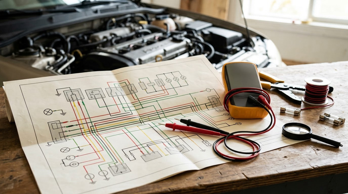
Learning how to read a wiring diagram for car repair comes down to three skills: knowing what the symbols mean, seeing how power and ground flow through a circuit, and being able to follow that flow across connectors, splices and control modules. A wiring diagram is a map of the vehicle’s electrical system, showing every wire, connector, fuse, relay, switch and ground point as symbols joined by lines. Learn to read it and a dead headlight stops being guesswork and turns into a short list of places to put a probe. Updated for October 2026.
The mistake most beginners make is treating the sheet as a picture of the car. It isn’t. It is a logic diagram: it shows how the circuit was designed, which is usually not how the circuit fails. The wire that looks fine on paper can be broken in half under a trim panel, and the diagram will never show that.
What the diagram genuinely does is narrow the fault. Once you can follow a circuit from its power source, through every switch and connector, to the load and back to a ground, you stop swapping parts at random. You test. That’s the whole difference between an hour of diagnosis and a weekend of parts.
Table of Contents
- What You Need
- Step-by-Step: How to Read a Wiring Diagram for Car Repair
- 1. Identify the Vehicle and Circuit
- 2. Learn the Diagram Symbols and Conventions
- 3. Separate Power, Ground, and Signal Paths
- 4. Trace the Circuit from the Symptom
- 5. Check Fuses, Relays, and Circuit Breakers
- 6. Test the Circuit Without Guessing
- 7. Diagnose Opens, Shorts, and Bad Connections
- 8. Verify the Repair and Clear the Fault Code
- Common Mistakes
- Safety and Final Verification Tips
- Frequently Asked Questions
- Can I use a wiring diagram from a different year or trim for my car?
- Why do car wiring diagram wire colors sometimes change?
- How do I find the ground wire on a car wiring diagram?
- What does it mean when a fuse keeps blowing?
- How do I test a wire for continuity with a multimeter?
- Should I replace a control module just because it appears in the diagram?
What You Need
Gather these before you open the first page, because chasing a missing tool mid-diagnosis is how small mistakes happen.
- Service information for your exact vehicle. The model year, engine code, transmission type and factory options all matter. A car with a different alternator or a different amp-rated fuse block is wired differently.
- The wiring schematic for that vehicle. Not a generic aftermarket chart. The factory schematic for your trim level, and the connector pinout drawings that go with it.
- A repair manual or service information subscription. The electrical section usually includes connector views, terminal layouts, wire color codes and location of junction blocks behind trim panels.
- A digital multimeter. Volts, ohms, continuity and ideally a millivolt setting for voltage drop. Almost every decision in this process comes back to this one tool.
- A test light or a small LED probe. Good for finding a live circuit quickly, and for confirming a dead one at a connector face.
- Fused jumper leads, test leads and alligator clips. Fused, because you will be bridging relay terminals and switch contacts sooner or later.
- Terminal tools. A pick or pin extraction tool, a small screwdriver set, heat-shrink and butt connectors, and crimps for the wire gauges in the harness.
- A battery charger or memory keeper if the car has modules that lose their settings when you cut power.
- Gloves and eye protection. Reading an electrical schematic is fine on a bench. Probing one under a dashboard is not.
A scan tool is worth having too, not to replace the diagram but to give you a symptom to trace. A stored code narrows which circuit to open first, which saves a lot of page-turning.
Step-by-Step: How to Read a Wiring Diagram for Car Repair
Work through these in order. Each one depends on the last, and skipping ahead is what turns a two-hour diagnosis into a guessing game.
1. Identify the Vehicle and Circuit
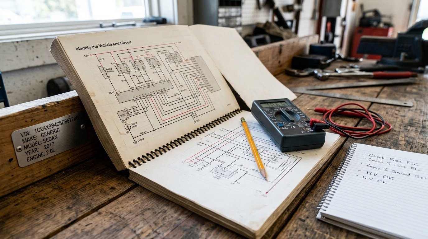
Confirm the vehicle before you read a single symbol. Check the model year, engine code, and the equipment level from the trim tag or the VIN plate, then match all of it to the diagram set. Factory diagrams are broken out by model year and often by engine or body style, and an option as small as a different alternator changes the sheet.
Then find the circuit. The back of most schematic sets has an index that lists circuits by name and circuit number, and each page carries a sheet number and a grid reference like 14-C-3. Write those down. Nothing is more annoying than realizing the continuation of the circuit you were tracing is on a fold-out page you folded shut ten minutes ago.
Look for three things in the circuit title: the circuit number, the fuse or relay that feeds it, and the ground point it returns to. All three are named on the sheet, which gives you your starting and ending points for free.
2. Learn the Diagram Symbols and Conventions
Symbols are the diagram’s alphabet, and the set is nearly universal across manufacturers even when the abbreviations are not. Learn these and you can read almost any automotive schematic.
| What you see on the sheet | What it means | What to check on the car |
|---|---|---|
| Two lines joined by a solid dot | A splice or junction. Current can pass in either direction. | Corrosion or a loose terminal inside the junction block. |
| One line crossing another with no dot | Not connected. The crossing is a drawing convenience. | Nothing. This is the classic beginner trap. |
| A connector drawn as a box or oval with numbered cavities | A connector. The letter is the connector ID, the number is the cavity. | Back-probe at the same cavity number, not by wire color. |
| An arrow, or a V shape, beside a connector | The male pin side. The V is the female socket side. | You are on the right side of the connector before you probe. |
| A small rectangle in line, labelled F | A fuse. Its number is printed beside it. | Fuse condition and, if it keeps blowing, the circuit behind it. |
| A zigzag or coil element in line, labelled FL | A fusible link, a heavy-duty feed near the battery. | Do not jumper it. Find the short first. |
| A box with a coil on one side and contacts on the other | A relay. The coil and the contacts are separate circuits. | Voltage at the coil, then voltage at the contact output. |
| A rectangle with a wavy filament, or a circle with a filament | A lamp or bulb. | Voltage on both sides, then the ground side. |
| A circle with an M, or a circle with a line through it | A motor or actuator. | Power feed, ground return, then the motor itself. |
| A shaded or outlined box with a component name and pins | A control module. Only the external pins are drawn. | Pin voltages with the circuit operating, never ohm-pinned live. |
| A dashed line | Internal wiring inside a module, or an option not fitted to your car. | Do not try to find a physical wire that does not exist. |
| Two wires drawn at the same switch terminal legend | Two separate switch contacts, used to prevent backfeed. | Never assume those two wires are connected to each other. |
Abbreviations on the sheet come next, because they appear before you can even interpret the symbols. Common ones: B+ or BAT for battery feed, ST or IGN1 and IGN2 for ignition positions, ACC for accessory, LP for lamp, GRD for ground, R and L for right and left, and STO for starter. Manufacturers vary, so treat the legend in your own manual as the authority.
One convention deserves repeating because it causes more wasted tests than anything else on the sheet: the arrows and V shapes next to a connector show which side has the male pins. They do not show the direction of current. Plenty of experienced people still read them as flow arrows, and then probe the wrong cavity.
3. Separate Power, Ground, and Signal Paths
Before tracing, classify every wire in the circuit. There are only a handful of types, and once you can name them you can predict what a meter should read at each point.
- Hot at all times. Constant battery positive, usually fused near the battery or the fuse block. Present whether or not the key is turned. Loss of this feed is what causes erratic, intermittent faults.
- Switched power. Battery voltage that only appears when a switch closes. If the load doesn’t work and there’s no switched power, the fault is upstream, in the switch, the relay or the fuse.
- Grounds. The return path. Grounding faults are the most commonly misdiagnosed problems on cars because the rest of the circuit looks perfect.
- Signal wires. Sensor returns, switch inputs, lamp drivers and pulse signals to a module. These are usually low current, and they are read with voltage while the circuit is active, not with a continuity test.
- Reference and data links. Things like five-volt references and communication lines between modules. They are drawn like signal wires but behave differently under test.
Every complete circuit needs all four working: power in, a switch or control, a load, and a ground return. That is your diagnostic checklist. A headlight circuit with no ground is identical to one with a blown bulb, and the diagram tells you which of the two you’re looking at.
4. Trace the Circuit from the Symptom
Start at the component that isn’t working, not at the battery. Working backwards from the symptom keeps you on the page where the failure actually is.
At the load, note the cavity number and wire color. Follow that wire in the direction of its power feed until you hit a connector, a splice, or a junction block. At each one, record the connector ID and cavity so you know where to find it in the car, then keep going.
Forum technicians have long recommended drawing the path out by hand on paper, with every connector, splice and switch marked in order. It takes five minutes and it catches errors before you touch a test lead. I do the same thing on the back of a parts receipt.
When the trace reaches a switch, pay attention to which terminals the contacts bridge in the position you’re testing. A headlight switch has separate contacts for low beam and high beam, and the diagram draws them as separate paths even when they share a terminal legend.
5. Check Fuses, Relays, and Circuit Breakers
A blown fuse is a report, not a diagnosis. It means current was flowing somewhere it shouldn’t have, and that could be a damaged wire, a shorted component, or water in a connector.
Read the fuse number off the schematic, then match it to the physical fuse box and confirm the correct amperage. A replaced-undersized fuse will hold the circuit down and is a fire risk. If a new fuse blows immediately, stop replacing fuses and go find the short.
Relays are cheap to test and easy to misread. Confirm the coil side has voltage when the switch should be on, then check for continuity across the contacts with the relay removed. A relay that clicks and passes no current is a failed contact, and it’s extremely common on older cars.
Watch for a fusible link near the battery as well. It looks like a heavier wire with a small element inside it, and it’s the last line of defence for the whole harness. Replace it with the same gauge and never bridge it permanently.
6. Test the Circuit Without Guessing
The diagram tells you what to measure. This is the order that keeps you from replacing good parts.
| Order | Test | Expected reading | What a bad reading tells you |
|---|---|---|---|
| 1 | Voltage at the load’s power pin, circuit fully operating | Battery voltage | No power here. Trace upstream, don’t replace the load. |
| 2 | Voltage on the ground side of the load, circuit operating | Close to 0 volts | A reading near battery voltage means the ground path is open or resistance is high. |
| 3 | Voltage drop across the ground path, load connected | Typically under 0.2 volts | More than that, and you have corroded or tight-corroded ground hardware to clean. |
| 4 | Voltage drop along the power feed, load connected | Typically under 0.5 volts | Find the connector, splice or crimp that eats the drop by testing either side of each one. |
| 5 | Continuity, power off, both leads on the same wire | Beeps or near 0 ohms | No continuity means an open circuit. Break the run into halves and repeat. |
| 6 | Resistance across a load, disconnected, one lead on each pin | A steady value that matches expectation | Open means the component is dead. Near zero means it’s shorted. |
One condition matters more than any other: a voltage drop measurement is only meaningful with the load connected and the circuit fully operating. Measure an idle circuit and the number tells you nothing, which sends people chasing faults that do not exist. If a reading confuses you, check the load is actually running first.
Never place an ohmmeter across a powered circuit. Disconnect the battery before any continuity or resistance work, and be careful with modules: a resistance reading taken through a control module’s internal circuitry is measuring the module, not the wire you care about.
7. Diagnose Opens, Shorts, and Bad Connections
An open circuit is a break anywhere in the path. Symptoms are a component that receives power but doesn’t return to ground, or a signal that never arrives. Bisect the run: test continuity from the load to the midpoint, then the midpoint to the source, and you will have the failing half in two tests.
A short to ground shows up differently. Fuses blow, the circuit smokes, or the battery drains overnight. Pull the loads off one at a time and watch whether the short disappears. If it does, you’ve found the section, and the module or component in it is the likely culprit.
High-resistance connections are the ones that come and go with heat, vibration and moisture. Look for green corrosion on terminals, swollen or discolored connector seals, and wire that has been repaired with tape or a butt splice crammed under a clip.
On a modified car, expect the diagram to be wrong. A previous owner who bypassed an interlock, jumpered an ammeter feed or added an amplifier may have moved, cut or coiled wires that appear nowhere in the book. When the diagram and the car disagree, the car wins; trace what is actually there and note the difference.
And don’t replace a module because it appears in the diagram. A control module is one of the last things to go, and only after power, ground, connector integrity and the inputs it depends on have all been proven good.
8. Verify the Repair and Clear the Fault Code
Put it back together properly. Re-seat every connector until it clicks, restore the terminal locks, and refit any split loom you had to open so chafe doesn’t take the circuit out again next winter.
Restore power and repeat the exact test that failed. Operate the system the way the driver does: turn signals, brake lights, headlights, wipers, the fan on high, the key start. A relay that tests fine cold can fail hot, and a marginal ground often passes with the meter attached and fails with the blower running.
Scan for codes, clear them, then drive or cycle the system until the monitor resets. If a code comes back, the fault is not fixed. A code that stays in memory with no current symptom usually means a recent repair, an open circuit the module saw once, or a genuine fault you haven’t found yet.
Finally, write down what you tested and what you found. Next time the same circuit misbehaves, you’ll have a real starting point instead of a blank sheet.
Common Mistakes
Almost every wasted afternoon traces back to one of these.
- Using the wrong diagram. Wrong year, wrong engine, wrong option level. The fix is a five-minute check of the VIN plate and build spec before you read anything else.
- Probing by wire color instead of cavity number. Colors repeat within a harness. Cavity numbers do not.
- Reading connector arrows as current direction. They mark the male pin side. Nothing else.
- Treating two wires at one switch legend as connected. They are separate contacts, deliberately, to stop one circuit backfeeding another.
- Measuring voltage with the load disconnected. A meaningless number sends you after a phantom fault for an hour.
- Replacing fuses instead of finding the short. Each new fuse is a small fire and a wasted part.
- Ignoring grounds because power looked fine. Check the return path first when a load gets power and does nothing.
- Testing a live circuit with an ohmmeter. Disconnect the battery first. Always.
- Damaging insulation or pinching a wire while working. A cut wire under a trim clip becomes an intermittent fault months later. Secure every harness you move.
- Trusting a diagram on a car nobody has kept original. Verify the actual routing on the vehicle before you pull a dashboard apart.
Two habits cover most of the rest. Write the circuit path on paper before you probe anything, and record the exact conditions of every measurement, including key position, engine state and whether the load was connected. A number without its conditions is a number you will misremember.
Safety and Final Verification Tips
Disconnect the negative battery terminal first, before any work that could leave a circuit live, and reconnect it last. If the car has modules worth preserving, put a charger on before you cut power. Some vehicles lose radio codes, window limits and idle settings, and those are separate problems from the one you were solving.
Never probe SRS or airbag wiring. Yellow connectors and yellow twisted-pair circuits are there for a reason, and a test lead across the wrong circuit can deploy the bag. Do the same with high-current fusible links and any circuit feeding a hybrid or electric vehicle’s high-voltage system; that work belongs with a technician who has the right equipment and the training.
When you bridge terminals to test a relay or bypass a switch, use fused jumper leads. A short across an unfused feed will damage wiring instantly, and copper is a poor substitute for a proper repair.
Clean grounds properly: remove the bolt, scrape to bare metal, treat the surface, and torque it down. A ground painted by the factory or clamped under a seat bracket is a fault waiting for a wet road.
Finally, know when to stop. Airbag, ABS, stability control, hybrid high-voltage and multiplexed body networks are worth handing to a qualified technician, and so is any diagnosis where your measurements keep contradicting the diagram. That mismatch is information, not failure.
Frequently Asked Questions
Can I use a wiring diagram from a different year or trim for my car?
Usually you can use it as a guide, but never as a final reference. Wiring changes between model years, engines and option levels, especially fuse ratings, alternator feeds, ground points and added circuits. Trace the same circuit on both diagrams and confirm the connector IDs and cavity numbers match your car. If they differ, the diagram for your exact build is the only one worth probing from.
Why do car wiring diagram wire colors sometimes change?
Because the codes follow the manufacturer’s convention rather than a universal standard. Most makers use a base color to show the circuit type and a stripe or solid secondary color to identify the wire within it, but what each color means varies by brand and year. Treat the color chart in your service manual as the authority, and use the color to help you find a wire, never to identify a cavity on its own.
How do I find the ground wire on a car wiring diagram?
Ground symbols are a set of short horizontal lines that get shorter as they stack, or a battery-style symbol with one line long and the rest short. Follow the load’s ground pin to the ground point named on the sheet, then look that point up in the connector and location views. The sheet also gives the ground’s cavity number, which is what you actually need to clean and tighten.
What does it mean when a fuse keeps blowing?
It means current is flowing where it should not be, or a load is drawing too much. A fuse that blows once may have taken an overload from a jam or a shorted device. One that blows every time you install a new fuse is a short to ground, and you should stop replacing fuses and start disconnecting loads to isolate the section. The schematic tells you which components sit on that circuit.
How do I test a wire for continuity with a multimeter?
Disconnect the battery, then set the meter to continuity or lowest ohms range. Place one probe on each end of the same wire and watch for a beep or a near-zero reading. A reading in the hundreds of ohms or an open result means the wire is broken somewhere. If the wire passes, move the load to the other end of the run and repeat to bisect the fault in two tests.
Should I replace a control module just because it appears in the diagram?
No. Modules are among the last things to fail, and they fail because of what feeds them, not because they appeared on the page. Prove battery feed, switched power, all grounds, connector integrity and every input signal before you consider one. If a module pinout is needed, read the pin voltages with the circuit operating, and never place an ohmmeter on a powered circuit.
Start by matching the diagram to your exact vehicle and drawing one circuit path on paper before you touch the car. Then work the test order: power, ground, continuity, voltage drop, load. If you can trace a circuit end to end, you can diagnose anything the harness runs, and you will do it in one sitting instead of three.